
Some features may be broke, sever upgrades where not smooth…
work in progress, last updated 9.1.2018
A little history and information about Granby Consolidation Mining at Anyox, BC
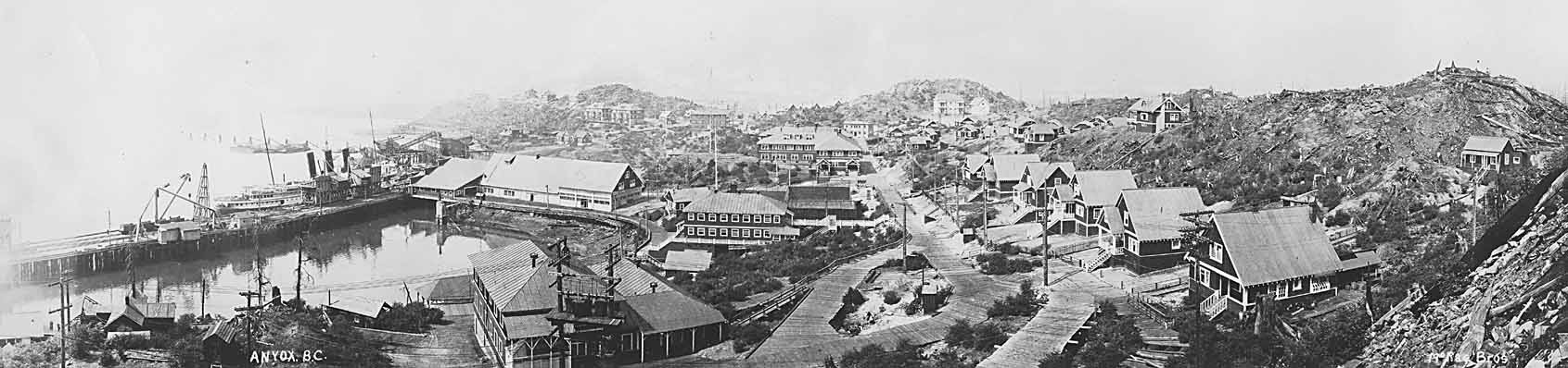
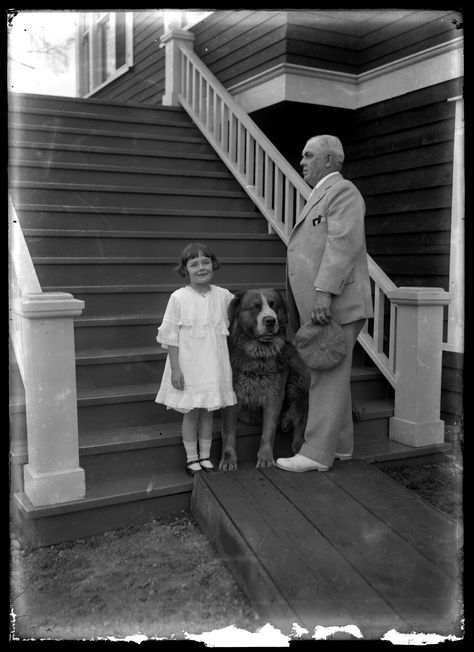
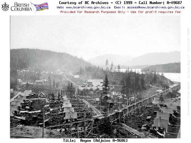
Anyox, BC 1911
Anyox is Canada’s largest ghost town that was operated by Granby Consolidation Mining from 1914 until the mines closed in 1935, primarily as a copper mine and smelter. The bulk of the original town has been destroyed; when the mine closed much of the town was salvaged. Then in 1942 a major wild fire burned most of the wooden structures down. The mine was largest producer of its time, in 1925 Anyox produced 38,207,434 pounds of copper! The actual claim originates from 1898, it was primary a copper mine but also had gold and silver. On July 31, 1935 the mine closed due to a few issues compounded. Minor strikes due to lower pay request with the prices of copper falling from the great depression and by an attempt to blast two open pit mines together to get the ore cheaper. The original open pit mine was called the “” hole”, 10 A.M. on November 27, 1934 whistles sounded for the largest explosive blast ever for the time. The method for estimating the explosive required for the blast was still experimental and too much was used. The blast not only shattered the ore, it collapsed many of the tunnels and fractured the rock surrounding the area making it unsuitable for tunnel mining. The tunnels under the glory hole at the deepest part of the mine where re-purposed to haul the ore out using the existing infrastructure to the town for processing where destroyed. For a much more in-depth read on the history of Anyox, check out this page! A guy named Frank Schlichting runs a Facebook group here, for his and other mine explores and to go on adventures with him! He has a vast YouTube Channel here with his videos of exploring abandon mines from all over! He has several small series on the Anyox mine and Gramby mines. The one embedded below this is his very best of, very good watch! I highly recommend you watch and check out his group and channel.
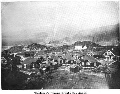
Residential part of the town:
At its peak the town was home to 2,500 to 3,000 people. Company built home where provided to all of its workers. The workers lived here tax free, paid by the company, with wages above the average for the work during this time period. Although the workers did pay rent, it was well below the cost of any comparable town. Utilities where included in the rent. The town had 2 sections for homes, flats adjacent to the mines and the slopes. Most of the mine workers lived in bunkhouses with the food and laundry provided by other workers. Some did live in family apartments and small single story homes. The nationalities of the workers where quite varied, some articles point to 15 different nationalities working at the mine.
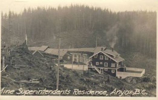
The white collar workers, shop keepers, plant workers and other upper management lived up on the hill in 2 story cookie cutter style homes. The largest homes where for highest ranked employees.
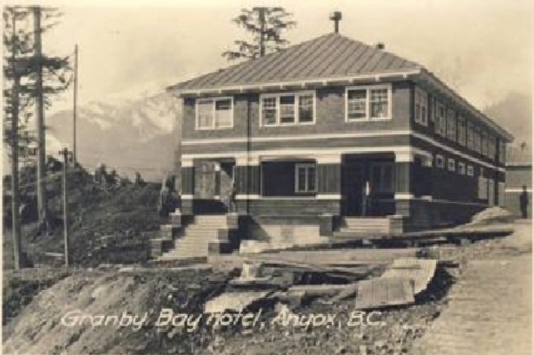
The town had 3 churches, a school, hospital, emergency room next to the mine, machine shops, and general stores, hotel, cemetery all on site for its residences.


The
change-house is a three-story frame building with concrete floors on the first and second stories.
The first floor Is occupied by a locker-room containing 300 steel sanitary lockers, a wash-room
where fifty men can wash at one time, a water-closet and urinal room, twenty-four shower-baths,
four porcelain tubs, and a drying-closet for clean clothes. The second floor consists of a pool
room, a library and reading room, a shift-boss’s office, an emergency hospital with four beds,
and a doctor’s office. The third story consists of a dance-hall with the necessary cloak-rooms.
This building is heated by an Arco sectional hot-water heater. A hot-water tank holding 1500
gallons attached to a separate heater provides hot water for the shower-baths.
Town’s Power:
220 Volts A.C. 3 Phase
120 Volts A.C. Single Phase
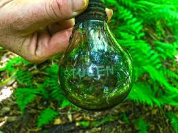
A well known story is the “Stolen” light bulbs. These where company light bulbs that had been etched to discourage employee theft of them; stories indicate this had little deterrence effect and some displayed them proudly in their windows. These are often prized fines of modern explores of the area.
“Stolen” Bulb:
120 Volts A.C. Single Phase
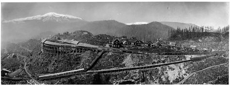
Hidden Creek Mine

The mine had 6 primary level, known as the 150, 230, 385, 530, 630, 700 and 2 open pit mines at the top called glory holes. The 385 level was the main haul line. With an in-mine crusher installed on the 230 level. The 150 level had the ore rail system for hauling the ore to town.
” The Hidden Creek mine in its initial development was opened up by six tunnels—namely,
the 150, 230, 3S5, 530, 630. and 700, which numbers are identical with the respective elevation of
each tunnel-level above sea-level. Fifty thousand feet of diamond-drilling was done prior to and
contemporaneously with this first tunnel-work. The diamond-drill cores established the general
outlines of the ore-bodies, and the tunnels served to develop them for mining at the most advan
tageous points. The haulage-tunnels are the 530, 3S5, and 150. The G30 and 700 were driven
to prospect the ore-body No. 2 and are now used only as stope manways. The 230 level is used
as a crusher-level only. On this level ore from the upper levels is crushed and dropped directly
into pockets extending to the i50 level, where it is drawn into railway-cars for shipment to the
smeltery.
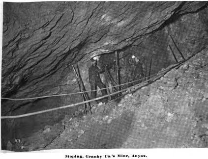
” Mining consists of open-stope or milling methods underground, and ‘ glory-hole ‘ or open-cut
work near the surface. Stoping was started first on the 530 level, extended to the 030 and 700
levels, and thence to the surface. These first stopes served as pockets from which the ore broken
above was drawn. By extending several stopes to the surface and widening them at the top,
two glory-holes of considerable size have been formed and are now being worked In ore-body
No. 2. An equal number has been developed in ore-body No. 1.
” The ore drawn from chutes on the 530 level Is transferred to pockets extending to the 3S5,
from which It Is delivered to the crusher-bins. Several raises have recently been completed
from the 385 level, into which all of the ore from the glory -holes in ore-body No. 2 runs direct,
thus eliminating the transfer on the 530 level.
“A departure from the general mining methods is being made below the 385 level, which
do not outcrop and have, a heavy overburden of rock to carry. In such places a system of
shrinkage stope is being developed which will give more support to the back and walls and
make working conditions safer. The method adopted in a section now under way consists of
shrinkage stopes 125 feet wide, with a length equal to that of the ore-body. Vertical pillars,
40 to 50 feet wide, also across the ore-body, are left between stopes.
” A mauway rise is driven through the centre of each pillar to the surface, or to other
workings opening to the surface. These manways serve for ventilation purposes and as
entrances to the stopes. Manway drifts are driven from the pillar raises into the stopes at
vertical intervals of about 30 feet progressively as the raises are advanced upwards. Drifts
are driven under the stopes, and chutes are distributed so as to draw evenly the ore broken
In excess of requirements for headroom In the stopes. Each chute Is equipped with a bulldozing chamber cut in the solid and without timber, as shown in an accompanying illustration. The
manway to this chamber is equipped with an air-line for use In drilling boulders.
” Electric Haulage in Granby-type Mine-cars.—The present haulage system is equipped with
75-cubic-foot, 24-inch gauge, Granby-type cars, of which there are fifty-four in use, and Ave 6-ton,
500- volt Westinghouse bar-frame locomotives. On account of the recent increase in smelting
capacity a change is being made in the haulage system on the 385 level, which handles the total
output to the crusher-bins. Thirty ears of 140-cubic-foot capacity and 36-Inch gauge, and also
two 12-ton Westinghouse locomotives of the bar-frame type, for pulling trains on the main line,
are being installed; and two of the 6-ton locomotives are being altered to fit the wide gauge
for switching purposes underground. The rails used with the light equipment weigh 30 lb. per
yard, while the new track is being laid with 45-lb. rails.
” A duplicate crushing plant has been provided, so that either piant can take care of the
maximum output. Crushing plant No. 1 is installed underground on the 230 level. Three crudeore
pockets extend from this level to the 3&5 and receive the run-of-mine ore from that point.
This ore feeds directly into the crusher, from which it can be diverted Into either of two pockets
extending to the 150 level. The Bacon Farrel crustier used in this installation has a solid-cast
frame and a crusher opening 36 x 42 inches. The crusher is belted to a line-shaft directconnected
to a 150-horse-power, 2,000-volt, Westinghouse alternating-current motor. Crusher
Xo. 2 is installed at the surface below two ore-bins of a capacity each of 250 tons. The ore
from these bins is fed directly into the crusher, from which it goes into pockets also extending
to the 150 level. The crusher at this point has a cast-steel sectional frame with a 30- x 42-inch
jaw opening, and it has a drive similar to that of the No. 1 crusher. The ore is crushed to 8
Inches, which is the size required by the smelting-works.
There where 5 ore bodies on the mine. Each one had a different composition that allowed a lot of the ore to be smelted on site with minimal imports. Allowing the town to even more self sufficient.
” Ore-bodies Nos. 2 and 3 occur in the schist area and both have an extensive outcrop.
The average elevation of the outcrop of those ore-bodies is 800 feet, and their continuity is
established down to an elevation of 350 feet. Ore-body No. 2 is a lenticular body about 400
feet wide, 300 feet thick, and 700 feet long, outcropping at the southern end and pitching to
the north at about 45 degrees. Ore-body No. 3 is much smaller and Is situated north-west of
No. 2 and geologically in the same area.
” The ore constituting ore-bodies Nos. 3, 4, and 5 is essentially a massive sulphide, although
in some parts of these ore-bodies siliceous zones with disseminated sulphides are found. Orebodies
Nos. 2 and 3 have disseminated sulphides in a schistose gangue, with an occasional small
lens of massive sulphide ore. There Is little evidence of oxidation or surface enrichment in the
ore-bodies, and unaltered sulphides appear at the surface. In Table II. is shown a general
analysis of the ore-bodies established by underground development-work and diamond-drilling.
In mining, calculated proportions from each ore-body are taken to make a mixture most desirable
for smelting.


Mine Power:
2,200 Volts A.C. 3 phase
220 Volts A.C. Single Phase
500 Volts D.C.
Trains!
Much of the ore was removed from the mine via trains on 150 level; bulk of them are electric. From the rail it could go to ore bins, a rock crusher or barge. Typically it was processed on site and smelted to sold as copper and shipped out. They also imported silver and other ores and fluxes to process materials.


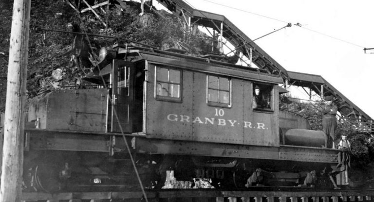

Train Power:
500 Volts D.C.
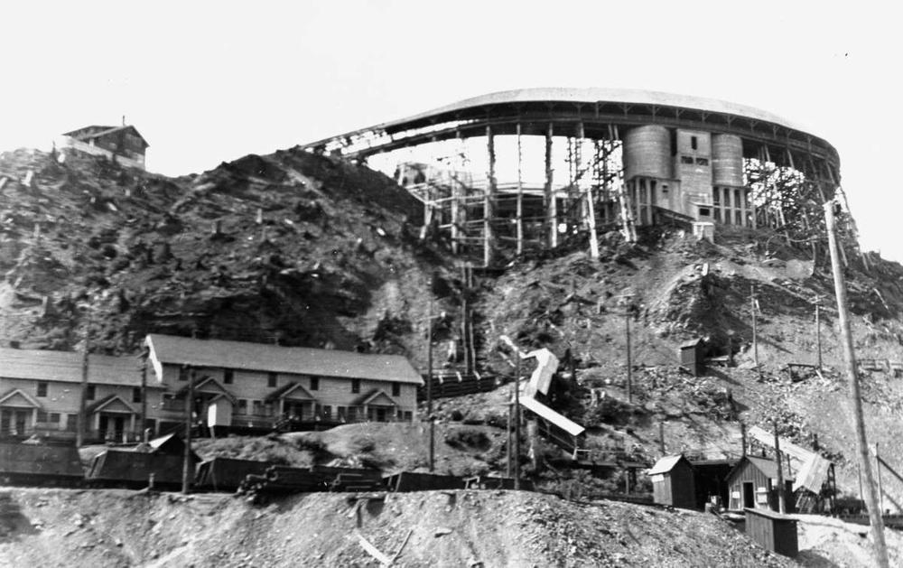
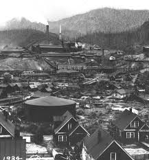
Smelter

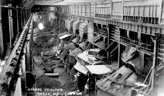
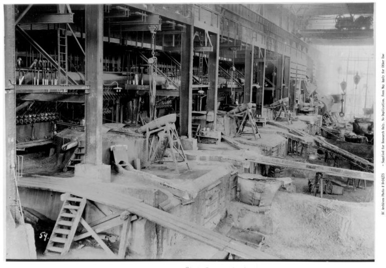
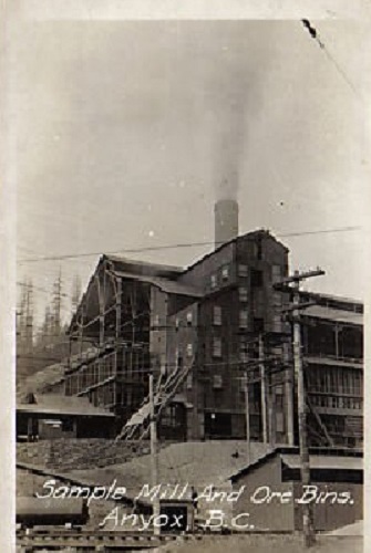
The whole smelting site operations was incredibly large; especially for the time and remoteness of the town.
The pictures just do not do it justice on the scale of operations that are taking place!
The smelting building pictured above, top of photo; the large building in the center is the power house.
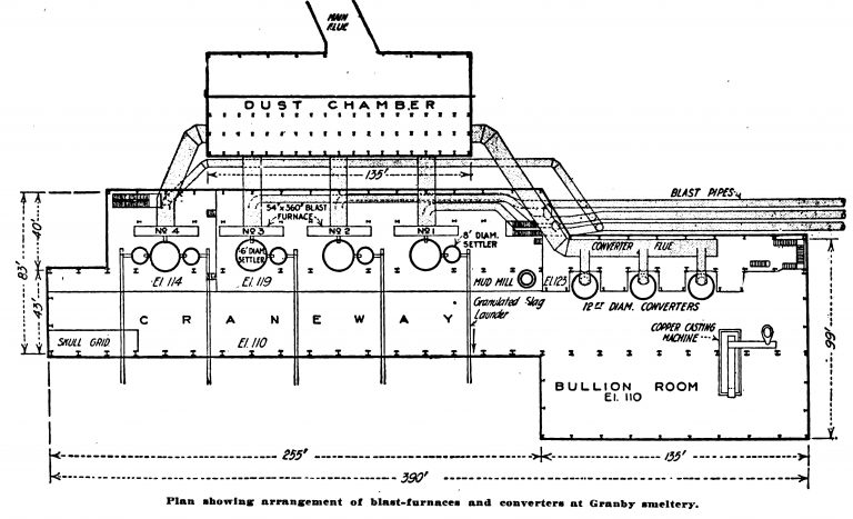
Below is the blueprints of the building with some of the actual pictures of the components directly below it in semi-relation to the print.


Blast Furnace with Settlers
Converters

Read more on the smelter ->
” Smelting-works.
” The smelting-works at Auyox, B.C., of the Granby Consolidated Mining, Smelting, and
Power Company was built primarily to treat the ores from its Hidden Creek mines, but also
with a view to handling other Granby and custom ores. Anyox is on the western shore of
Observatory inlet, in north-western British Columbia ; the mines and the smelting and power
plants are all within a comparatively short radius of the town. There are five distinct ore-bodies
developed by the Granby Company, known as Nos. 1, 2, 3, 4, and 5; they are irregular coppersulphide
ore-bodies In metamorphosed sedimentaries—schists, slates, and limestones—cut by
dykes. Oxidation has been only slight and sulphides are found where the ore-bodies come to
the surface.
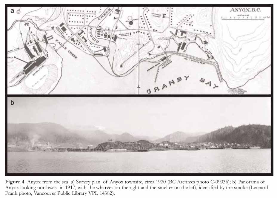
“When selecting the site for the plant, the three main considerations were: (1) Plenty of
slag-dump room for future years; (2) sufficient ground for future enlargement of plant; and
(3) availability of water-power. Since the mines, smeltery, and wharves had to be connected
by railroad, minimum up-grades were provided from wharves to smeltery, and practically level
grade from the mines to the smeltery. It Is estimated that there is room at the site selected
for 12,000,000 to 20,000,000 tons of granulated slag. On account of the steep, glaciated hillsides,
all natural benches are narrow, and the one selected for the site was as wide and long as could
be found in this vicinity. Falls creek, at the north end of the site, presented the only near-by
water-supply available. An economical power arrangement was obtained by Installing a highpressure
water-pipe line from the dam to the power-house, which is at the foot of the hill near
the mouth of Falls creek. All timber and underbrush, and a layer of muskeg covering the
surface of the ground to a depth varying from 2 to 8 feet, were removed, and all footings placed
on rock or on a glacial-gravel foundation.
” From the plans it will be noted that the ore-bins arc not directly back of the furnaces, but
are situated to one side, making an angle of about 80 degrees with the Hue of the furnaces.
The charge-trains enter the feed-floor between the furnaces and converters, and the sampler is
at the end of the bins next to the furnace building. The arrangement is not exactly ideal, but,
because of the length and narrowness of the bench, it was the best that could be designed under
the circumstances, and in practice it has worked satisfactorily.
” The furnaces and converters are In one building. The building is a steel structure with
wooden roof, having an asbestos covering. It Is 80 feet wide and 390 feet long, having concrete
retaining-walls both in front of and back of the furnaces. The furnace-floor elevation is 119
feet and converter-floor elevation 110 feet above sea-level. A common crane runway 40 feet
wide serves both departments upon which operates two Niles, direct-current, 500-volt, 40-ton,
quick-acting cranes with main and auxiliary hooks of the same size. In the southern end of
the building there were originally three furnaces. Later a fourth was added.
” The long axes of the furnaces are in line and parallel to the long axis of the building.
The furnaces are of the rectangular-bosh type. The original three furnaces are 50 x 3C0 inches
at the tuyeres, which are of 4 inches diameter and spaced 10.S inches from centre to centre.
There are two tiers of jackets. The lower jackets are 10 feet G inches high and 4 feet G inches
wide and rest on heavy, water-jacketed base-plates; the upper jackets are 6 feet 8 inches high
and 5 feet wide. The furnace is supported by heavy-steel H columns and 20-inch box-type
mantel-beams. These are exceptionally well braced with heavy I-beams and girders. Jackets
and tuyeres are of the welded type. The latter are of the Anaconda type with ball-and-socket
joint. Furnaces Nos. 1, 2, and 3 measure 13 feet 2 inches from the tuyeres to the top of the
upper jackets, while on No. 4 furnace, which has a third tier of jackets, this distance is IS feet
2 inches, the extra 5 feet of height having been gained by lowering the settler floor. With this
exception No. 4 furnace lias the same measurements. Steel water-jacketed spouts, having a trap
of 15% inches, discharge over a bronze-nose jacket and give excellent service. Cooling water
which is ice-cold the year round ensures the permanence of a thick, protective crust which is
never ‘hulled’ through a campaign. The furnaces work under a 45- to 50-oz. blast and use
900 cubic feet of air per minute per foot of furnace-length.
“Each furnace is served by one 10-foot and one S-foot settler having a 9-inch chrome-brick
lining. The brick stands. 9 inches away from the shell, the intervening space being filled with, lightly tamped backing, consisting of common bats crushed to % inch, from which the fines have
been removed by screening. At the tap-holes, of which there are two. 18 inches of chrome brick
is used without backing. The tapping-block is a magnesite brick having a 1-ineh hole, embedded
in a plate of converter copper. Due to the frequency with which matte is tapped, a tapping-bar
is rarely needed. Aside from renewing brick at the tap-holes, which is necessary about once
a month, very little repairing or lining is necessary. The cooling spray has been abandoned.
Slag flows from the 16-foot settler to the S-foot settler, thence to the granulating-launders. An
appreciable amount of matte is recovered from the second settler. Granulated slag is deposited
on the dump through launders lined with slag plates and having a fall of % inch to the foot.
” The feed-floor is at an elevation of 145 feet. The furnace-tops are constructed of heavy,
cast-iron lintels and columns, all well bound and braced. The side walls and ends are bricked
with 18 inches of red brick, and the semicircular steel hood is lined with firebrick. A steel
down-take, 9 feet in diameter, leads the gases from the furnace to the dust-chamber.
” Charge-tracks, of 3-foot gauge and 56-lb. rails, run on either side of the furnace and
continue out of the building to the converter-slag bins and sintering-plant bins. The Anaconda type of steel charge-cars of 5-ton capacity is used. Trains of twelve cars each are hauled by
a 12-ton, Baldwin-Westinghouse, electric locomotive. There are two of these trains In service.
Cars are dumped by overhead, horizontal, compressed-air cylinders running on trollies, two to
a furnace, one on each side.
“The manner of charging the furnaces is their most striking feature. The charging-space
Is divided into three sections by the columns supporting the lintels. The original bevel plates
were removed and in their place were built hoppers with horizontal bottoms and cast-plate sides.
They are 2 feet 6 Inches deep and the bottom plate overhangs the top of the jackets !) inches.
At the back of the hoppers, held under the charge-floor, are heavy cast-iron ploughs operated by
compressed-air pistons in cylinders working under 100-lb. pressure. The capacity of each hopper
is j,0OO lb. of charge and each section has two, making twelve in all per furnace.
” When the charge Is needed in the furnace, air is turned on and the plough pushes the
charge from the hoppers into the furnace. Any hopper can be operated independently and the
amount charged at any one time can be controlled. This arrangement permits charge-trains to
lie damped and released without having to wait for the charging of the furnace. In this system
of feeding the proper overhang with the proper drop of the ore have to be determined to get
the right distribution of coarse and flues, so that the furnace may run properly. The amount
of drop and overhang depend upon the character of the ore and whether or not it is desired to
feed to the middle or to the jackets. It Is possible to place the charge in any desired plnce and
to favour any particular section of the furnace. The main idea was not original with the Granny
Company, but was taken from Sticht’s description of the smelting practice at Mount Lyell. The
Urnnby Company worked out the mechanical details to suit its own construction only. The idea
was first tried out on No. 4 furnace, and as the experiment showed a tendency toward smoother
running of the furnace and kept it in better shape than any of the others, It was decided to
adopt this feed system on the three remaining furnaces.
” In the northern end of the building there are three 12-foot, Great Falls type, electrically
operated converters, each having twelve tuyeres of V*/n inches diameter. Punch-rods are upset
to l^j inches and tuyeres reamed with 1%-inch bar. Blast-pressure is 13 lb. and air-oonsuniption
from 0,000 to 7,000 cubic feet per minute per converter. Indies of 85-cubic-foot capacity are used,
Imt are being replaced by ladles of 120-cubic-foot capacity. Converter-slag at present is poured
Into the settlers of furnaces smelting the ore charge. Charges of copper weigh about 8 tons and
are cast into flat, bevel-edged bars measuring 30 x IS x 3 inches. A straight-line casting-machine
Is nsed which dumps the bars into a coollug-tank, after which they are conveyed to the castingfloor.
The blister-copper averages 09.25 per cent. Cu.
“The slag-skull grid is at the top of a steel bin having a sloping bottom and chutes for
discharging the contents into railroad-cars. The top of the bin measures 12 x 45 feet, and is
In Id with 12-inch I-benms running lengthwise and supporting 12-foot lengths of 90-lb. rail laid
< ro«swlse and spaced 7 inches apart. Skulls are dumped on this grid, and pieces not sufficiently
broken by the fall are further reduced by hand. Part of one man’s time is required for this
work.


On July 13, 1921 the smelter caught fire. As of writing this I do not have a cause or injury report. Smelter is top of photo, power house bottom right.

Smelter Power:
2,200 Volts A.C. 3 phase
120/220 Volts A.C. Single Phase
500 Volts D.C.
480 Volts A.C. 3 Phase (not confirmed, motor list suggest it had 440vac induction motor listed)
Power House
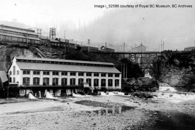
Power Plant #1 was responsible for all of the towns power and most of the air to run equipment. It had 9 control panels in it for the several power sources it housed. The pen-stock had an effective head of water of 375 feet giving it a nominal 165 psi of hydraulic pressure to drive the plant.
Input air compressor data here
input electrical data here

Gen Desc Here
” Power Plant.
“The mines, smeltery, and hydro-electric power plant of the Granby Consolidated Mining,
Smelting, and Power Company at Anyox, B.C.. are situated on the west shore of Observatory
inlet an arm of the sea on north-west British Columbia. Ores from the Granby Company’s
Hidden Creek mines at Anyox are mined and smelted together shipped in by boat from the outside. Fuel, fluxes, and all supplies are brought in by steamship
and unloaded at the company’s wharves, from which they are distributed to the mines and
various plants by the company’s railroad. Power for the various operations of the Grauby
Company is secured from a hydro-electric power plant which utilizes the water from Falls
creek, and from a 6,000-horse-power steam plant which operates during the winter months when
there is a decreased water-supply.
” Falls creek, a stream of considerable size emptying into Granby bay at the north end of
the smeltery-site, receives its flow from melting glaciers. The surrounding hills are steep and
provide but little chance for storage. The company constructed a crib and rock-fill dam 110 feet
high at a suitable point a mile distant, where the canyon is narrow and the stream could be
deflected over a natural rock spillway 125 feet wide. From this dam the water is taken by a
0-foot wood-stave pipe down the creek and across the north end of the smeltery-site to the power
house. This plant is situated just below the smeltery and well toward the mouth of the creek.
From the smelting plant to the power-house the penstocks are of steel, with branches leading to
the various Pelton wheels. The arrangement and location of the pipe-line.gives a water-pressure
of 110 lb. at the smeltery-site. The head of water on the Pelton nozzles at the power-house is
375 feet, the effective head giving a pressure of about 165 lb.
” The power-house is a brick-and-steel structure and al} foundations are on solid rock.
A 15-ton crane running the entire length of the building handles the heavy machinery. The
water-discharge from the Peltons is a little above the high-tide water-mark on Falls creek.
The building is 50 feet wide by ISO feet long and has concrete floors. In this building are
installed the following: One Nordberg variable – capacity water – wheel – driven two – stage aircompressor,
with cylinders 22 and 3G x 42 inches, running at 84 r.p.ni., with a capacity of
4.000 cubic feet of free air per minute delivered at 100-lb. pressure; one Nordberg water-wheeldriven
special converter blowing-engine with duplex cylinders, 60 and 60 x 48 inches, running
at 75 r.p.m. and giving a capacity of 20,500 cubic feet of free air per minute delivered at 16-lb.
pressure; three Conuersville high-pressure blast-furnace blowers, having a displacement of 400
cubic feet of free air per revolution and each with a capacity of 45,000 cubic feet of free air
per minute at 4S-oz. pressure. The Pelton-wheel buckets are directly bolted to specially designed
fly-wheels. The blowers are connected by chain drive to 500-horse-power motors, and can be
driven either by water or electric power. A pipe system leads to the furnaces and converters
from the blowers, and high-pressure air is delivered to the mine by 9-inch and 6-inch pipe
lines. There are two direct-connected motor-driven pumps taking water from the raceways and
delivering it to condensers at the steam plant.
” The present hydro-electric plant consists of two 03S- k.v.a. alternators, with two 700-horsepower
overhung Pelton-Doble water-wheels to each alternator. Alternating current at 2,200 volts
is generated by Westinghouse GO-cycle three-phase alternators. They are separately excited by
two 50-kw. Westinghouse motor-generator sets, one of which has an overhang water-wheel on an
extension motor-shaft for initial starting. The excitation voltage Is 125 volts. The 6-foot
pipe-line from the dam branches to 25-inch pipes outside the power-house for delivery to each
wheel. The effective head used is 372 feet. The 25-inch lines divide again at a Y near the
Peltons into two 18-inch pipes, one of which leads to each wheel. The water-wheel driving the
exciter is fed by an 8-inch pipe.
” There are two 300-kw. motor-generator sets, supplying direct current at 550 volts, for
railroad and smeltery use. The generators are type M Westinghouse, and each is driven by a
440-liorse-power, 2,000-volt, three-phase, GO-cycle, Westinghouse type CCL induction-motor.
” Switchhoard Control in Fifteen Panels.—The switchboard is divided into fifteen panels.
A syncbronoscope is mounted on a bracket together with two voltmeters, one for each machine,
and below these there Is a Tirrel voltage-regulator. The first panel controls the street-lighting,
which is a Westinghouse series tungsten system with a constant-current transformer on a gallery
over the board. The second and third panels control the two generators. On them are mounted
three ammeters, one for each phase, an indicating wattmeter and one three-pole, type B oilswitch
; also there are a double-pole field-switch of 400 amperes, a main field-rheostat, an eightpoint
voltage receptacle synchronism plug, and a reversing-switch for operating the pilot governor
control on the generator. Panel No. 4 has 125-volt, direct-current excitation. On this panel are
mounted voltmeters and ammeters for each machine, a field-rheostat, two double-pole 400-ampere
field-switches, and one 200-ampere double-pole double-taken from the transformer or from the exciter bus as desired. Panel No. 5 Is a totalizing panel
on which is mounted a 3-ammeter, type TG static ground detector, a TI power-factor meter, a
2,400 kw. polyphase graphic wattmeter, and a type C watt-hour meter. Panel No. 6 controls the
two 75-horse-power motors driving direct-current generators for excitation. Panel No. 7 controls
the mine-feeder. The mine is supplied by one three-phase line from the town circuit for use iu
case of emergency. There are three ammeters on this panel, a circuit-breaker, and a watt-hour
meter. Panel No. S controls the smeltery power-feeder. All the alternating-current motors in
use around the smeltery and shops are connected to this circuit. Panel No. 9 controls the
smeltery-lighting, town-lighting, and power circuits. On this panel there are two ammeters, one
to each circuit, operating through meter-plugs to enable the reading of each phase. There are
two circuit-breakers, one to each circuit, and two watt-hour meters. Panel No. 10 is for the
440-horse-power motors in connection with the motor-generator sets. Panels Nos. 11 and 12
control the direct-current side of the motor-generator sets. On each panel are mounted one
carbon-breaker, one voltmeter, one ammeter, a field-rheostat, and a three-pole knife-switch. Panel
No. 13 controls the railroad circuit and is provided with a circuit-breaker, an SPK switch, an
ammeter, and a Columbia wattmeter. Panel No. 14 controls the direct current supplied to the
smeltery for cranes, 12-ton locomotives, and some direct-current motors. All the cables between
the boards and the machines are rubber-covered and braided. Stranded 220-volt, three-conductor,
and single-conductor cables are laid in Orangeburg fibre conduits.
‘• Five-panel Switchboard at Sab-station.—All the power supplied to the mines goes to the
mine sub-station, where there is a five-panel switchboard connecting incoming and outgoing
power-lines. The outgoing Hues are on No. 2 panel, which has one three-phase, 2.200-volt powerline
for motors. No. 3 panel has two single-phase lines for small motors and heating and lighting
around the plant. The fourth panel controls the motor for the motor-generator set which supplies
500-volt direct-curent for ore-haulage. The fifth panel controls the direct-current genera
tor.
” The board at the sub-station is a Westinghouse type similar to the one at power-house
No. 1, and with the panels similarly equipped.throw switch for power-house lighting,with Granby and custom ores
Tooltip content
Dam

Incomplete Worker Deaths List:
| Mine | Date | Name | Occupation | Cause of Death | |||||
|---|---|---|---|---|---|---|---|---|---|
| Phoenix | October 18, 1917 | John Nerhus | Miner | Killed by falling rock. | |||||
| Hidden Creek | February 9, 1917 | Mike Radeka | Miner | Killed by falling rock from back of stope. | |||||
| “May-Beatrice” | June 21, 1917 | Nick Gullune | Laborer | Skull fractured by fall of rock. | Hidden Creek | July 30, 1916 | Guest Hill | Chuteman’s Helper | Electrocuted by striking trolley-wire with a steel bar he had over his shoulder. (would be 550VDC) |
| Hidden Creak | July 21, 1917 | P.A. Gustafson | Brakeman | Crushed between end of car and side of chute. | |||||
| Hidden Creek | April 26, 1918 | Aime Rennie | Barman | Crushed to death by fall of rock. | |||||
| Hidden Creek | May 2, 1918 | Eli Utivich | Chuteman | Much crushed skull and badly bruised body which proved fatal. | |||||
| Hidden Creek | February 21, 1916 | John Bensen | Miner | Killed by sliding rock in chute. | |||||
| Hidden Creek | June 7, 1916 | James McEwen | Miner | Struck by falling rock, causing injuries from which he died two hours later. | |||||
| Hidden Creek | June 7, 1916 | Robt. H. Jones | Miner | From same day falling rock issue causing lacerated leg. Died 3 hours later from heart failure. | |||||
| Hidden Creek | July 15, 1916 | Ernest Larson | Miner | Struck by flying rock from shot, causing internal injuries, ribs broken; died four hours later. | |||||
| “May-Beatrice” | June 21, 1917 | Nick Gullune | Laborer | Skull fractured by fall of rock. | Hidden Creek | July 30, 1916 | Guest Hill | Chuteman’s Helper | Electrocuted by striking trolley-wire with a steel bar he had over his shoulder. (would be 550VDC) |
Sources of information used:
https://www.rdks.bc.ca/sites/default/files/docs/Anyox_Powerhouse_SOS_Final.pdf
https://open.library.ubc.ca/collections/bcbooks/items/1.0222817#p67z2r0f:Anyox
https://journals.lib.unb.ca/index.php/GC/article/view/10249/10642